Wankel Rotary Engine Redesign
Summary
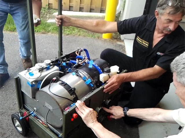
I joined a small engineering startup company with a mobile power generation product in development – and several big customers who were quite interested in purchasing. At the heart of the product was a small, air-cooled Wankel rotary engine that was designed for use in large RC and autonomous aircraft and was purchased by the startup. However, due to the substantial difference in application, the engine required many modifications before it could serve its purpose in a power generation application. I worked with – and eventually led – a group of engineers to redesign the engine to suit the application and prepare all of its component for mass production and assembly.
Goal
Redesign Wankel rotary engine subsystems for operation in a mobile power generation product.
Approach
Not having much of a background in the complex field of combustion chemistry, I was relieved to join the startup knowing that the design of the combustion chamber did not require modification; in fact, the entire engine design had been purchased from a company that creates engines for RC and autonomous aircraft. These engines were selected for use in the product due to their high power-to-weight ratio; however, since the mobile power application for which the startup intended to use the engine differed so greatly from an aircraft application, there were, inevitably, some issues with using them in the product.
The primary problem concerned overheating. The original engine designs were air-cooled since, in an aircraft application, there is ample flow of very cool air available to cool the engine. This is not so in a stationary power generation product, especially when the engine is packaged in the product for safety and aesthetics. In order for the product to be successful, more heat had to be removed from the engine.
The engine heat also had a major impact on the rolling element eccentric shaft bearings, which failed long before their design life. We made an early decision to investigate the use of hydrodynamic bearings as this would not only potentially increase the longevity of the engine but would also serve as an additional means to cool the engine core. This design choice was made easier by the existence an oil system in the air-cooled design meant to feed the rolling element bearings and rotary seals during operation; this meant we could modify the existing system to suit the needs of fluid bearings.
The theory of the operation of hydrodynamic bearings is centered around Reynolds Equation, which itself is derived from the Navier-Stokes equation when applied to a viscous film between moving surfaces. The Reynold Equation, being a nonlinear partial differential equation, does not generally admit analytical solutions except for highly simple geometries and boundary conditions. Numerical solutions are possible, however, and this had led to the proliferation of design graphs for use by engineers who seek a functional hydrodynamic design without the need to perform many numerical simulations for their specific geometries.
To make use of this method, several design choices are initially fixed, such as the bearing length to width ratio, rotational speed, lubricant viscosity, and radial clearance. Knowledge of the load is used to compute nominal pressure. The charts are then used to determine other dependent variables, such as oil flow rate and minimum film thickness. All of the data in hand are then used to compute the resultant force which, if that force does not match the initial loading assumption, are adjusted and the process repeats, iteratively, until convergence.
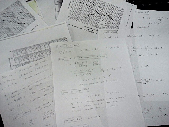
Initially, I attempted to do this by hand using a bearing design textbook that provided the design graphs and tabulated data. I found that convergence could take many iterations, which was quite time-consuming to carry out, and I was also interested in the effect that many types of lubricant oil and alternative bearing length to width ratios may have on the final design; consequently, I quickly realized that a computer would have to be involved in this design process to execute it efficiently and accurately.
I used the tabulated data from the textbook that describes the design graphs to create design functions for which interpolation was possible. (If I were to do this again, I’d probably lean on curve-fitted design functions .) Intermittent calculations were scripted and everything was assembled into a single function that could be placed in a loop to be run until convergence. The code was then run using a range of initial bearing designs and lubricant choices so that we could select the oil type and bearing geometries that best suited the use case and provided the most robust solution.
Finally, to increase our confidence that the solution we selected was sensible, I created, meshed, and solved the oil cavity geometry for the bearings using ANSYS Fluent – our most sophisticated computational fluid dynamics tool – to confirm some of the pressure and flow estimates of the design.
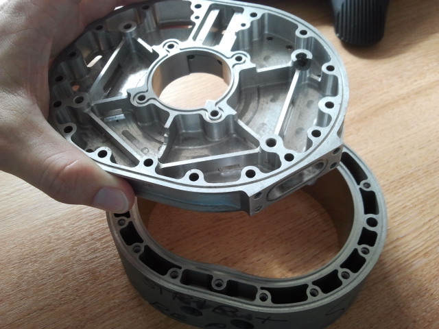
Unfortunately, moving from rolling element bearings to hydrodynamic would not be sufficient to solve the overall heating issue. To pull more heat from the engine, an axial liquid cooling scheme was adopted. Axial cooling schemes were fairly common in products at this time (both Mazda and Audi have used this type of cooling successfully in their Wankel engines) and, drawing inspiration from extant designs, we arrived at an axial cooling design in which the team had a pretty high degree of confidence.
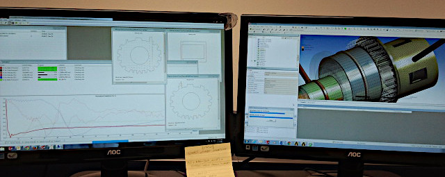
In mass production, the end plates that mate with the engine housing (and seal the coolant chamber) would be cast due to their complexity; this struck me as a good opportunity to use a new software tool to optimize the flow with low-risk design modifications. The startup used SolidWorks as its primary CAD tool, and with that came SolidWorks Flow Simulation. I used this tool to analyze the flow of the coolant through the axial channels and, using the solutions as a guide, create small fin features inside of the housing that directed coolant to maximize flow over the hot bow and reduce the probability of fluid stagnation or backflow. I do wish I had kept a picture of the final design since the fins made this component very interesting to look at!
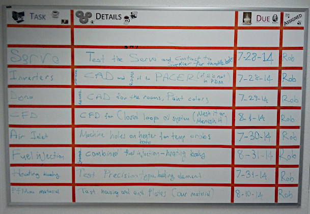
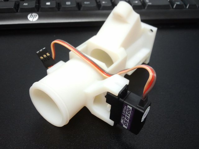
There were many other design modifications that were required to make the engine successful, including: changes to hardware, modifications of the throttle body geometry, servo throttle control, and far too many others to list here. I enjoyed taking on as many tasks as I could, and I was very happy when the company leadership asked that I become the lead mechanical engineer.

To make the design truly successful, careful tolerance stack-ups were conducted on the assembly in preparation for mass production. Parts were designed for manufacturing and assembly from the ground up, and the engineering team was in constant contact with the machining team to develop an understanding of the fabrication techniques that would be used in production, and the metrology that would be used to enforce the GD&T requirements – this was very useful for understanding how to design better, cheaper, and less complex components.
The project was a mountain of work in a very traditional mechanical engineering field, and I thoroughly enjoyed it. I had the opportunity to lead a small group of engineers through a very technical process using advanced analysis tools. It was an opportunity to hone universal engineering skills and see a complex product through the development phase up to the point of production.